Every subsystem on this board, traced to the exact device-tree node that enables it — and marked where the upstream CanMV v3 reference describes a board that is not ours.
SoC file
canaan/k230.dtsi 857 lines, 56 nodes
Reference board
canaan/k230-canmv-v3-lcd.dts 96 lines
Our board file
nix/dts/k230-tdisplay.dts compiles to 55,156 bytes
Kernel
ruyisdk/linux-xuantie-kernel pinned 7d4e1f4
Observed so far
U-Boot, then Linux to a root shell 2026-09-20; no peripheral but the card
the board
Four things a product render can prove
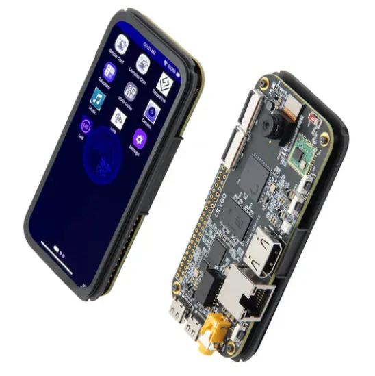
A 4.1″ AMOLED slab on a K230D. The picture below is LilyGO’s own
product shot and the markers are placed by eye. The authoritative map is the
fan-out that follows: the device tree cares which pad a thing hangs off, not
where it sits on the board.
RM69A10 568×1232 AMOLEDcamera · MIPI CSIRF moduleK230D, approximately
Only four markers, because only four things are identifiable in a render. The connectors along the bottom edge — USB-C, HDMI and the card slot are all present per LilyGO’s pin table — have not been told apart here, and guessing at them would be the wrong kind of confident. Component identities come from the schematic and the vendor BSP; positions are eyeballed.
fan-out
Nine paths off the pads
Each path carries the bus or pin group it uses and the device-tree node that
has to exist before Linux sees it. Colour says which file the node lives in,
not how well it is known — only one row on this diagram has been
exercised on hardware.
Pad assignments read out of this board’s own U-Boot pinmux (u-boot/arch/riscv/dts/k230_canmv_v3p0.dts, whose model string is the one U-Boot prints on our hardware) and cross-checked against the FPIOA alternate-function table in machine_fpioa.c. Node names and status come from the Xuantie tree at 7d4e1f4; the violet nodes come from nix/dts/ in this repository and compile, which is not the same as working.
subsystems
Which file carries which node
Left: the hardware and its pins. Right: where the node lives — blue for
the SoC k230.dtsi, plain ink for the reference board
.dts, violet for what this repository had to write.
declared in k230.dtsi
from the reference board .dts
written in nix/dts/
not established
ConsoleCH342 ch0 IO38 TX · IO39 RX 115200 8N1
The SoC file declares five identical snps,dw-apb-uart nodes,
all disabled, and aliases serial0 to uart0. The
board file flips uart0 on and points stdout-path
at it.
Only uart0 and uart3 are ever enabled, so the
kernel will register ttyS0 and ttyS3 and there
is no ttyS1 — which the SDK’s default environment
nevertheless asks for.
k230.dtsiuart0: serial@91400000 status = "disabled"
The whole display chain — display-subsystem,
vo@90840000 and dsi@90850000 — is already
status = "okay" in the SoC file, wired VO → DSI
by an endpoint pair. A board file’s only job is to hang a panel off
&dsi port 1.
The reference -lcd variant does that by including
display-st7701-480x800.dtsi. Same reset pin, same enable pin,
entirely different panel.
ours, written and compilednix/dts/display-rm69a10-568x1232.dtsi
TouchGT9895 @ 0x5d I²C3 on IO36/37 RST IO24 · INT IO23
Our pins are identical to the reference LCD board’s touch
wiring — reset-gpios = <&gpio0_ports 24>,
interrupts = <23 IRQ_TYPE_EDGE_FALLING>, confirmed
against the schematic. Only the chip and its address change.
The node is written and inert. Mainline has never carried a GT9895: at
v6.18 goodix_berlin matches only
goodix,gt9916, and the binding enumerates
gt9897 and gt9916 and nothing else.
k230.dtsii2c3: i2c@91408000 status = "disabled"
reference — different chiptouchscreen@38 compatible = "edt,edt-ft5306"
ourstouchscreen@5d compatible = "goodix,gt9895"
Wi-FiRTL8189FTV SDIO on MMC0 EN IO45
The schematic ties WIFI_CLK/CMD/D0–D3 to the SoC’s
MMC0 balls — the dedicated pads, not FPIOA pins.
The RT-Smart board defconfig agrees:
CONFIG_REALTEK_SDIO_DEV0=y.
Power is a rail, not a reset line: IO45 enables an RT9080-33 LDO that makes
WIFI_3V3. Our board file carries the reference’s
&mmc_sd0 block over unchanged and adds nothing, so nothing
asserts IO45 under Linux either. That is a known gap, not an oversight.
carried over verbatimokay; no-1-8-v; rx_delay_line = <0x0d>; tx_delay_line = <0xc0>;
not writtenno mmc-pwrseq, no regulator, no cap-sdio-irq — unresolved
Storagemicro-SD MMC1 on IO54–59 4-bit · 50 MHz
The card is the boot device, and the one path on this page with an
observation behind it: U-Boot enumerated it, listed its partitions and
read our three files off the ext4.
The reference settings carry over unchanged. This is the one storage path
where our board and the CanMV v3 agree exactly.
carried over verbatimokay; no-1-8-v; cap-sd-highspeed; mshc_ctrl_r = <0x00>;
USB2 × OTG USB-C + host
Two canaan,k230-otg controllers, both disabled in the SoC file,
both switched on by the board file with no further properties. Nothing
board-specific to do.
k230.dtsiusb0: usb@91500000 usb1: usb@91540000
carried over&usb0 { okay; } &usb1 { okay; }
AudioInno codec I²S
Unusually, the codec and the I²S controller are already okay in
the SoC file. The board file supplies only the machine-level glue node that
binds them into a sound card.
The NPU (gnne plus ai2d), the GC8000UL GPU, the
video codec and the whole security subtree are enabled in the
SoC file and never mentioned by any board file. They cost a new board port
nothing — and, in the GPU’s case, give it nothing either: no
Mesa or Vulkan driver exists for that part.
Present on the board, absent from every device tree in play. The SoC file
declares i2c0–i2c4 and
spi0–spi2, all disabled; the U-Boot pinmux
muxes IIC0 onto IO48/49 and IIC4 onto IO7/8. Which of those the PMIC hangs
off, and which SPI and chip-select the radio uses, is not something this
survey established.
not establishedread the schematic nets before writing any of these nodes
a trap
The pinmux is not in this device tree
Worth saying plainly, because it inverts the usual expectation:
k230.dtsi and every board .dts in this family contain
no pinctrl node, no pinmux, no
pinctrl-names, and no regulators of any kind.
A grep for all of those across the Linux device-tree files returns nothing. GPIO
banks exist as gpio-controllers, so a driver can ask for pin 22
— but nothing in the Linux device tree decides that pin 22 is a GPIO rather
than OSPI_D6. That decision is made one stage earlier, in U-Boot’s
own device tree, which drives the FPIOA block at 0x91105000 through
pinctrl-single:
u-boot/arch/riscv/dts/k230_canmv_v3p0.dts
&iomux {
pinctrl-names = "default";
pinctrl-0 = <&pins>;
pins: iomux_pins {
pinctrl-single,pins = <
// lcd_rst
(IO22) ( 0<<SEL | … | 1<<IE | 1<<OE | 15<<DS | 1<<ST )
// hdmi_int,gpio← on this board it is the touch INT
(IO23) ( 0<<SEL | … )
// hdmi_rset ,gpio← on this board it is the touch reset
(IO24) ( 0<<SEL | … )
// LCD_EN
(IO25) ( 0<<SEL | … | 7<<DS | 1<<ST )
// i2c3
(IO36) ( 1<<SEL | … ) → IIC3_SCL// BT_UART_TXD← also wrong; SEL=1 on IO37 is IIC3_SDA
(IO37) ( 1<<SEL | … )
(IO45) ( 0<<SEL | … ) → plain GPIO; the schematic calls it IO45_WIFI_EN// MMC1 -> TFCARD
(IO54) ( 2<<SEL | … ) → MMC1_CMD
>;
};
};
numbering
Two GPIO banks, and the off-by-32
The SoC file splits 64 pins into two controllers of 32, and each numbers its own
pins from zero. Every GPIO our board file references lands in bank 0, so the trap
never fires — the Wi-Fi enable would be the first thing to cross into bank 1,
and nothing references it yet.
Each canaan,k230-apb-gpio-port numbers its own pins from zero. Writing <&gpio1_ports 45> for the Wi-Fi enable would be out of range on a 32-pin controller; writing <&gpio0_ports 45> would be silently wrong. The index is 13.
Board evidence: the V1.0_NEW schematic, the vendored U-Boot device tree
k230_canmv_v3p0.dts, the RT-Smart k230_canmv_v3p0_defconfig, and machine_fpioa.c.
The hardware observation is the first-boot console log committed under docs/evidence.
House rule in force: observations outrank vendor source, and a datasheet grounds
nothing. Anything not read out of a file, a schematic net or a console is marked
unestablished above.
 RM69A10 568×1232 AMOLED camera · MIPI CSI RF module K230D, approximately